We’d like to remind Forumites to please avoid political debate on the Forum.
This is to keep it a safe and useful space for MoneySaving discussions. Threads that are – or become – political in nature may be removed in line with the Forum’s rules. Thank you for your understanding.
📨 Have you signed up to the Forum's new Email Digest yet? Get a selection of trending threads sent straight to your inbox daily, weekly or monthly!
The Forum now has a brand new text editor, adding a bunch of handy features to use when creating posts. Read more in our how-to guide
RTS replacement issues - *Jan 26 update*
Comments
-
There are two live tails outgoing from the meter, labelled LL and LLL. LL is the fourth tail for the constant circuit, LLL the fifth for the switched circuit*. The cable labelled water heating from the RH Henley block is in fact the whole unrestricted feed, currently powering everything but the storage heaters. I can't see how the installer could have separated the feed to the bottom immersion heater element from the rest of the constant circuit without going outside the meter cupboard. He could perhaps just have terminated the switched circuit tail LLL in a new 3p Henley block, but this would have left the householder with no (storage) heating, which I suspect is a no-no for RTS replacement meter engineers. In any case, completing the job is the householder's responsibility, not the supplier's - says me.Phones4Chris said:The mistake that was made is that the tail for the Water Heater "off-peak consumer unit" has been connected into the Henley Block for the 24/7 supply when it should have been connected into a Henley Block on the ALCS off-peak supply (which hasn't been fitted). It should have been very obvious to the installer that this tail was the off-peak water heating
I wonder what instructions the installer gave @giant_among_ants before departing.
* My OVO engineer labelled them LC and LS. I had to ask - so now I can't unknow what the labels mean.I'm not being lazy ...
I'm just in energy-saving mode.0 -
If the LLL was connected to a Henley Block the Storage heater feed would still be connected to it, so to say he would have had no storage heating is completely wrong!!Ildhund said:
There are two live tails outgoing from the meter, labelled LL and LLL. LL is the fourth tail for the constant circuit, LLL the fifth for the switched circuit*. The cable labelled water heating from the RH Henley block is in fact the whole unrestricted feed, currently powering everything but the storage heaters. I can't see how the installer could have separated the feed to the bottom immersion heater element from the rest of the constant circuit without going outside the meter cupboard. He could perhaps just have terminated the switched circuit tail LLL in a new 3p Henley block, but this would have left the householder with no (storage) heating, which I suspect is a no-no for RTS replacement meter engineers. In any case, completing the job is the householder's responsibility, not the supplier's - says me.Phones4Chris said:The mistake that was made is that the tail for the Water Heater "off-peak consumer unit" has been connected into the Henley Block for the 24/7 supply when it should have been connected into a Henley Block on the ALCS off-peak supply (which hasn't been fitted). It should have been very obvious to the installer that this tail was the off-peak water heating
I wonder what instructions the installer gave @giant_among_ants before departing.
* My OVO engineer labelled them LC and LS. I had to ask - so now I can't unknow what the labels mean.
There are TWO tails coming from the RH LL Henley block, not one, look at the picture again.
It is obvious that the Water Heater feed was a timed circuit and should therefore be connected to the LLL, NOT LL. (The other tail is the 24/7 feed for the other circuits).
ONLY IF there are other circuits on that Water heater feed that are required outside of off-peak times would the householder have to get an electrician to alter something in the CUs. My understanding from what @giant@giant_among_ants has said is, it's not the case but he'll have to confirm.
Edit: Oh and the reason for those added two Henley blocks in the first place was that the original tail for the 24/7 circuits was not long enough to go direct to the meter, and of course two N feeds were needed. (LH block).0 -
Phones4Chris said:ONLY IF there are other circuits on that Water heater feed that are required outside of off-peak times would the householder have to get an electrician to alter something in the CUs. My understanding from what @giant@giant_among_ants has said is, it's not the case but he'll have to confirm.And *that's* why I would appreciate a photo of the CUs.OP has said they have two CUs They currently have three live tails (2x 24h, 1x timed). The detail of which tail goes where is important.CU2 appears to contain both 24h and timed circuits:CU1 one main switch, controls sockets, lights and cookerExactly how the three sections of CU2 receive their power is key to this mystery.
CU2 three main switches. (A) controls storage heaters; (B) controls the bottom water heater; (C) controls the panels, convectors and top water heater (boost).N. Hampshire, he/him. Octopus Intelligent Go elec & Tracker gas / Vodafone BB / iD mobile. Ripple Kirk Hill Coop member.Ofgem cap table, Ofgem cap explainer. Economy 7 cap explainer. Gas vs E7 vs peak elec heating costs, Best kettle!
2.72kWp PV facing SSW installed Jan 2012. 11 x 247w panels, 3.6kw inverter. 35 MWh generated, long-term average 2.6 Os.0 -
Correct! Which is why I qualified my original comments "BUT as already said, need to the pictures of the CUs to be able to positively confirm."QrizB said:Phones4Chris said:ONLY IF there are other circuits on that Water heater feed that are required outside of off-peak times would the householder have to get an electrician to alter something in the CUs. My understanding from what @giant@giant_among_ants has said is, it's not the case but he'll have to confirm.And *that's* why I would appreciate a photo of the CUs.OP has said they have two CUs They currently have three live tails (2x 24h, 1x timed). The detail of which tail goes where is important.CU2 appears to contain both 24h and timed circuits:CU1 one main switch, controls sockets, lights and cookerExactly how the three sections of CU2 receive their power is key to this mystery.
CU2 three main switches. (A) controls storage heaters; (B) controls the bottom water heater; (C) controls the panels, convectors and top water heater (boost).
From what the OP has said it would appear it should be 1 x 24/7 feed from the meter and 2x Off-peak feeds for the different sections of the CU(s).0 -
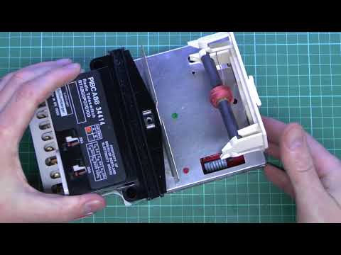
If as was likely both the 25A and the 80A live from the RTS - driven by the comfort meter (top RHS) - was going to the restricted / heating CU - then I tend to agree that a new Henley is required and the port 5 feed split to supply it.Not the exact model - but suspect wiring the same on this one.But I keep looking at the piccies - and sometimes convince myself their is 3 live tail connections from that new Henley - and then panic and think no - it's just the dirty white tape. And that their are 6 tails going out on the old - including a 2nd neutral I dont have - but can see clearly in the new piccy.I think the OP had 2 neutral and 4 live beforeN - daymeter to CUL - day CU (*)N restricted and 24/7 comfort rate meter to CUL1 - live - domestic heating label (*)L2 - restricted NSH ? 80AL3 - restricted HW ? 25A (*)It strikes me now L,L1 and L3 are now all on the Live Henley port 4 - L3 no longer restricted.Leaving OP at the mercy of his thermostat if leaves active - or paying day rate if uses water.So L3 if existed needs a new Henley block driven by port 5. But going by OP's wording that is what he had.But would be nice to see four ?? seperate input isolator switches in CUs - to make sure actually was 4 input and not output fuses / MCBs etc.Or of the OP could tell us how main tails on the new Live Henley - as if only 2 outputs blows my theory completely.But based on mine - if look at CU you wouldn't know what tails were driving which - unless you stripped it down - you'd have to take that on trust to some extent based on labeling and function.But given the OPs reported problem - the L3 moving seems a logical conclusion. But both those connections looked identical - so will need to check out they get the right one if others have lost wording etc.0
-
So sorry that these tired old eyes didn't spot the cable sneaking out of the bottom of that Henley block. That does indeed make a nonsense of what I wrote.Phones4Chris said:
There are TWO tails coming from the RH LL Henley block, not one, look at the picture again.Phones4Chris said:
I rather thought the two blocks were just the existing ones repurposed, probably put there when all the cabling was renewed some time after the meters were installed in 1993. So, it might be possible to force the supplier to come back and correct their fault by parting the LLL tail to insert a new Henley block in the gap and transferring the water heating cable to the new block. There might still be some work needed in the CUs nevertheless.
Oh and the reason for those added two Henley blocks in the first place was that the original tail for the 24/7 circuits was not long enough to go direct to the meter, and of course two N feeds were needed. (LH block).I'm not being lazy ...
I'm just in energy-saving mode.1 -
@Ildhund well yes those two Henley blocks are repurposed BUT in view of @scot_39 's most recent remark "But I keep looking at the piccies - and sometimes convince myself their is 3 live tail connections from that new Henley - and then panic and think no - it's just the dirty white tape."
Hmmm. I've looked yet again on a very zoomed in view and @QrizB I reckon that maybe we all need to go to specsavers!! I think maybe it isn't just the dirty white tape and there are indeed two tails coming out of the bottom of that RH Henley block which would make sense as -CU1 one main switch, controls sockets, lights and cookerThose CUs would require TWO 24/7 Live feeds, one for CU1 the other for CU2 (C) and TWO off-peak feeds CU2 (A) and CU2 (B). In a way the two 24/7 feed should have been obvious and a silly error to miss it BUT still NOT relevant to the fact that the Off-peak Water Heater should be connected to the LLL from the meter not LL in that RH Henley block.
CU2 three main switches. (A) controls storage heaters; (B) controls the bottom water heater; (C) controls the panels, convectors and top water heater (boost).
@giant_amongst_ants can you please look closely at that RH Henley Block (move the water heater tail slightly if needed) and confirm that there are two tails coming out the bottom of it.
Can we also (just for our clarity) have pictures of the CUs (all open as I previously asked so we can see the Main Switches, breakers and etc.).
As I've understood it, the only issue you have complained about is the loss of Off-peak feed to the bottom water heater - CU2 (B) and this, as I've already said, is fixed by SP coming back and fitting a Henley Block to the Meter LLL (off-peak) output for the Storage Heater feed and moving the Water heater feed from the other existing Henley block to the new one.0 -
When I look at that RH Henley - the new 24/7 live - when really zoom
 If really zoom in You can see the looped over from top exit with label.You can see the central tap from the rhs going straight downAnd you can see a little bit of scuffed cable that to me is too wide and appears to be heading out of the meter cabinet more left to right - than the bottom central cable that looks to be slightly right to left - and the other starting to go is it behind - is that a tiny little bit of the centre cable appearing just as goes out of view ? or just a shadow / the "heating" tail from the top of the Henley..I believe its also from the LHS of that piece of grey tail - to the RHS of the central point cable - too wide to be the same cable..And at this zoom - you can see the tape ending - so its not cream tape its scuffed grey tail.So the OP has 4 CU isolators - he seems firm on that - and potentially as above 3 lives from meter port 4 and that Henley and only one restricted.But I could just be going mad.As my post above we need the OP to check."Or of the OP could tell us how main tails on the new Live Henley - as if only 2 outputs blows my theory completely."So is it top and centre bottom - or top, left bottom and centre bottom - grey tails.And on the old system - there no obvious termination point for what could have been 25A out and 80A out - but it was pretty crowded in the middle there. And I may just have been reading too much into the ops reference to boost - as my RTS did the boost - and had two indendent outputs to do so.0
 -
I did wonder if that was 2 tails coming out of the bottom which if is the case then it is simply another Henley and connect the water heater to the LLL / storage heaters which will be via a complaint to the supplier. So there should be 2 tails going to CU 1 and 4 to CU 2 which, depending on access / location, may or may not be visible. The problem will of course be getting anyone at the supplier end to understand what is actually wrong.1
-
Instead of all this speculative "theory" and reference to 25A or 80A which has nothing to do with the key point, why don't we just wait for @giant_among_ants to come back and tell us.Scot_39 said:"Or of the OP could tell us how main tails on the new Live Henley - as if only 2 outputs blows my theory completely."So is it top and centre bottom - or top, left bottom and centre bottom - grey tails.And on the old system - there no obvious termination point for what could have been 25A out and 80A out - but it was pretty crowded in the middle there. And I may just have been reading too much into the ops reference to boost - as my RTS did the boost - and had two indendent outputs to do so.
Your query about whether it was two tails coming out of the bottom of that Henley block was the only thing of relevance!0


 https://youtu.be/bDfioJkTaoI?t=218

Confirm your email address to Create Threads and Reply

Categories
- All Categories
- 353.5K Banking & Borrowing
- 254.1K Reduce Debt & Boost Income
- 455K Spending & Discounts
- 246.6K Work, Benefits & Business
- 602.9K Mortgages, Homes & Bills
- 178.1K Life & Family
- 260.6K Travel & Transport
- 1.5M Hobbies & Leisure
- 16K Discuss & Feedback
- 37.7K Read-Only Boards