We’d like to remind Forumites to please avoid political debate on the Forum.
This is to keep it a safe and useful space for MoneySaving discussions. Threads that are – or become – political in nature may be removed in line with the Forum’s rules. Thank you for your understanding.
📨 Have you signed up to the Forum's new Email Digest yet? Get a selection of trending threads sent straight to your inbox daily, weekly or monthly!
The Forum now has a brand new text editor, adding a bunch of handy features to use when creating posts. Read more in our how-to guide
Ground Source Heat Pumps
Comments
-
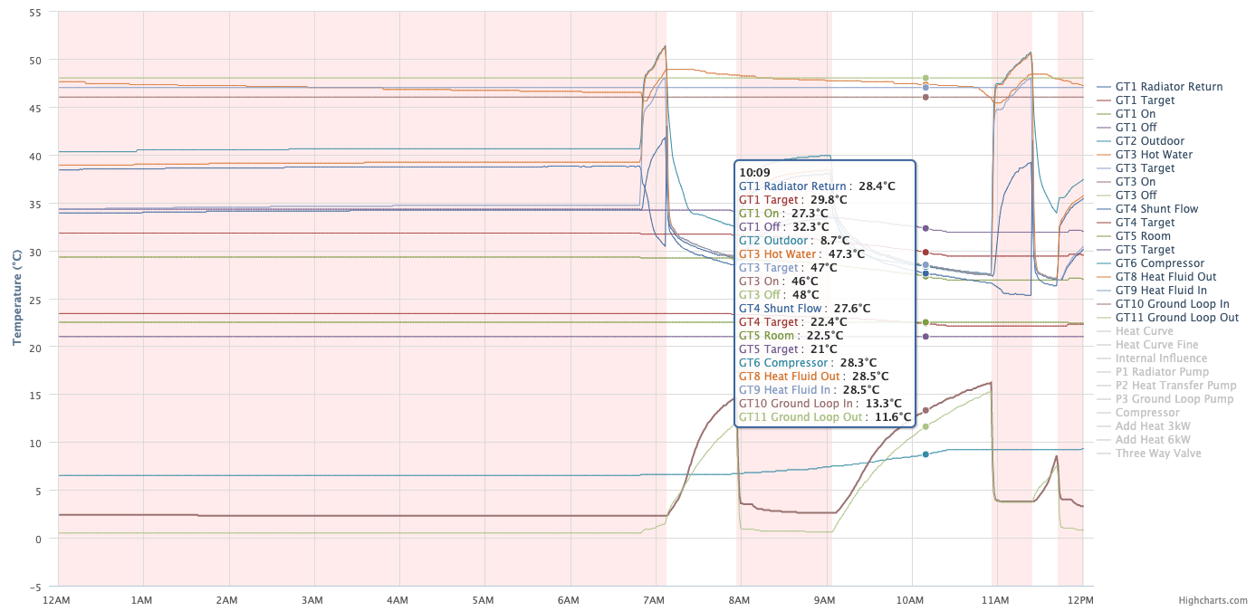
I built my own monitor (interface / capture / visualisation) years ago running on a RasPi which I think I've mentioned on here before, so would be interested to know what extra the H66 can do.beardymarrow said:Oh, and get yourselves a Husdata H66. It's an absolute god-send for tweaking stuff (and no, I'm not on commission :-)) graphing the results etc. I used to have an H20 which serial connected to my home PC, but the H66 is standalone (and talks MQTT if you want to integrate into Home Assistant or whatever). House data, Your heat pump in the smart home - Your heat pump in the smart home (husdata.se)
1 -
From the rego simulator and confirming it against reality from my heat pump. The curve charts in the manual are OK, but the text says that at 0deg slope 4 the return temp would be 35, but it's not, it's 32.8 :-)DazzlerDazza said:
Fantastic
Temp Target = ((20 - OutdoorTemp) * Slope / 6.25) + 20 + FineTune + ((RoomTarget - RoomTemp) * RoomInfluence).
Here's a Rego simulator (not written by me) -https://u.pcloud.link/publink/show?code=XZAxVhVZ3F6aRfUIEsFGfR8u6sSQkHVOE87k in case that's useful too. I'm trying to remember if you've mentioned this before... Did you reverse engineer this from Rego microcode or just from the curve charts in the manual + knowledge of how the internal influence works?
Yeah, I saw that article, and thought to myself "Yeah, so what, that's just normal isn't it :-)"DazzlerDazza said:
I assume you all saw the BBC News article the other day about heat pump geeks?
https://www.bbc.co.uk/news/business-64261457
The OpenEnergyMonitor stuff they are doing looks interesting:
https://heatpumpmonitor.org/
In order to calculate COP, however, am I right in thinking that you'd need to install an expensive heat meter (flow rate + temperature)?
Would be good to be able to monitor the flow rate, as the rest for COP is easy (return temp, flow temp and electricity consumption).0 -
I think Beardy suggested opening the value to the UFH circuit more. If that works, you can keep the lower flow temp and higher efficiency.lstevensuk said:
Thanks @Strummer22 that's exactly what I was trying to ask. Is it better to have it at a low (currently I'm on 4.6 and +0.5) or boost that up and see if the UFH can get hotter. That room takes about 6hrs from 15c to 19c if I'm lucky at the moment.
I forgot that you said you had an IVT. Mine is a more modern system with a smart thermostat which controls the central heating pump. When it turns the central heating on, the cold water in the rads returns to the heating buffer tank, prompting the heat pump to start up. The heat pump attempts to warm the heating buffer tank to whatever the weather compensation settings say the flow temp should be. In practice, it generally doesn't quite get up to the set point while the central heating is on - my pump has an inverter and I've turned the compressor down to 50% of max output to improve efficiency. I have only needed to adjust this upwards during the very coldest spells. So even though my big, draughty house has radiators sized for oil central heating, they work well enough at ~40C flow temp. The trade-off is that the heating is on and the heat pump running for 10+ hours a day in winter. However, I must be doing something right because the COP was about 4.4 in December and 4.7 in January.0 -
Yeah, you've basically done what the H66 does, except it uses an ESP32, not a Pi. Other than that, not much difference. It can set values as well via the web interface or MQTT, so you can change the settings that way.DazzlerDazza said:I built my own monitor (interface / capture / visualisation) years ago running on a RasPi which I think I've mentioned on here before, so would be interested to know what extra the H66 can do.
0 -
Yeah, the mix valve, so that more of the hot water from the pump goes through the UFH.Strummer22 said:I think Beardy suggested opening the value to the UFH circuit more. If that works, you can keep the lower flow temp and higher efficiency.
I forgot that you said you had an IVT. Mine is a more modern system with a smart thermostat which controls the central heating pump. When it turns the central heating on, the cold water in the rads returns to the heating buffer tank, prompting the heat pump to start up. The heat pump attempts to warm the heating buffer tank to whatever the weather compensation settings say the flow temp should be. In practice, it generally doesn't quite get up to the set point while the central heating is on - my pump has an inverter and I've turned the compressor down to 50% of max output to improve efficiency. I have only needed to adjust this upwards during the very coldest spells. So even though my big, draughty house has radiators sized for oil central heating, they work well enough at ~40C flow temp. The trade-off is that the heating is on and the heat pump running for 10+ hours a day in winter. However, I must be doing something right because the COP was about 4.4 in December and 4.7 in January.
4.4 and 4.7 COP is awesome. That's the beauty of the newer GSHPs with the variable output compressors, much less cycling. Our is on or off :-:smile:0 -
Any chance that's on Github? Just curiosity.... I wouldn't have a clue on how to wire it up!beardymarrow said:
Yeah, you've basically done what the H66 does, except it uses an ESP32, not a Pi. Other than that, not much difference. It can set values as well via the web interface or MQTT, so you can change the settings that way.DazzlerDazza said:I built my own monitor (interface / capture / visualisation) years ago running on a RasPi which I think I've mentioned on here before, so would be interested to know what extra the H66 can do. 0
0 -
Unfortunately not. I keep intending to tidy it all up into a state that might be shareable, but just never got round to it.Any chance that's on Github? Just curiosity.... I wouldn't have a clue on how to wire it up!
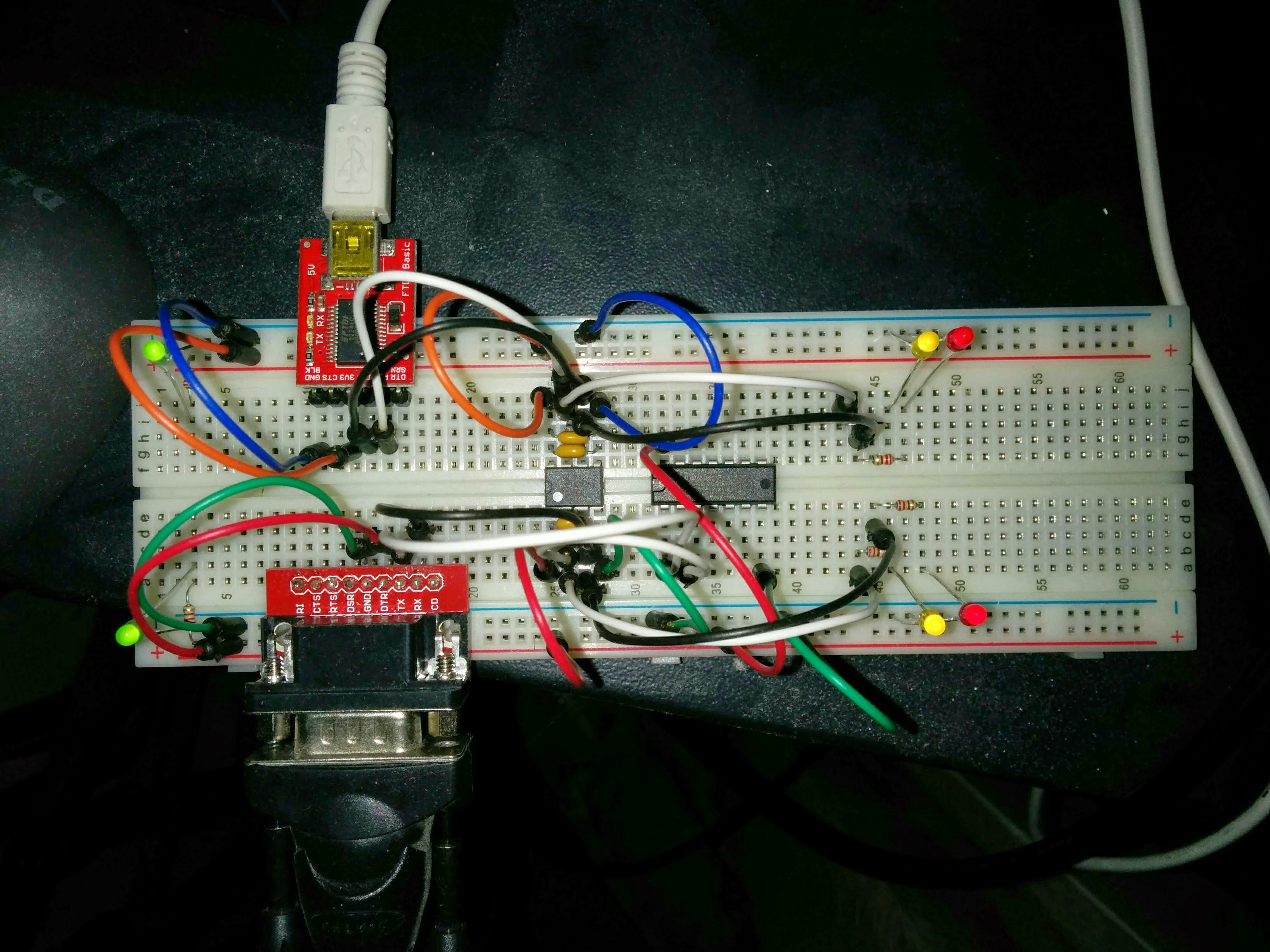
And the hardware interface I built looks like a right dog's breakfast!
That was only ever meant to be a first rough prototype, but it's been in place, connected to my heat pump for 9 years now - and I dare not touch it! It's probably massive overkill for what it does (I am certainly no hardware engineer) and a ready-made solution like the Husdata H66 would probably suit most people.
1 -
I'm sure I've tested it just using a RS-232 TTL level interface? Looks like you've got opto-isolation on there, which is a good idea?DazzlerDazza said:
That was only ever meant to be a first rough prototype, but it's been in place, connected to my heat pump for 9 years now - and I dare not touch it! It's probably massive overkill for what it does (I am certainly no hardware engineer) and a ready-made solution like the Husdata H66 would probably suit most people.0 -
Yes - it uses an opto-isolator, as recommended by the guy I sourced a lot of the information from:
https://rago600.sourceforge.net/
I didn't really fancy potentially breaking anything so I just went with the advice given.Communication always using 19200 bps, 8 bit, no parity, 1 stop bit (19200/8N1). This is 5V CMOS 4000 (TTL) signals, which must be connected by galvanic separator. In that case we will use optocoupler for separation. There are available optocouplers for example MCT6, ILD2 or equivalent1 -
Yeah, that's a brilliant resource. I used it loads when reverse engineering the rego 637.DazzlerDazza said:Yes - it uses an opto-isolator, as recommended by the guy I sourced a lot of the information from:
https://rago600.sourceforge.net/
I didn't really fancy potentially breaking anything so I just went with the advice given.Communication always using 19200 bps, 8 bit, no parity, 1 stop bit (19200/8N1). This is 5V CMOS 4000 (TTL) signals, which must be connected by galvanic separator. In that case we will use optocoupler for separation. There are available optocouplers for example MCT6, ILD2 or equivalent0
Confirm your email address to Create Threads and Reply

Categories
- All Categories
- 353.5K Banking & Borrowing
- 254.2K Reduce Debt & Boost Income
- 455.1K Spending & Discounts
- 246.6K Work, Benefits & Business
- 603K Mortgages, Homes & Bills
- 178.1K Life & Family
- 260.6K Travel & Transport
- 1.5M Hobbies & Leisure
- 16K Discuss & Feedback
- 37.7K Read-Only Boards


