We’d like to remind Forumites to please avoid political debate on the Forum.
This is to keep it a safe and useful space for MoneySaving discussions. Threads that are – or become – political in nature may be removed in line with the Forum’s rules. Thank you for your understanding.
📨 Have you signed up to the Forum's new Email Digest yet? Get a selection of trending threads sent straight to your inbox daily, weekly or monthly!
The Forum now has a brand new text editor, adding a bunch of handy features to use when creating posts. Read more in our how-to guide
Electronic connection on cross trainer

MRGANNET
Posts: 120 Forumite
in Techie Stuff
Not sure if this is the right place for his question or if it's more DIY?!
I purchased a second hand elliptical cross trainer and unfortunately in the process of getting into my van for transport, one of the leads which connects to the display panel broke away from its connection....I have no idea what these things are called so I've attached photos!!! Basically the small wires have all broken away from the red connection box. Is this an easy job to fix which I could do myself or is it a specialist job?
https://photos.app.goo.gl/NsJVLfVLJtGF59Gw6
https://photos.app.goo.gl/JnfViQrJy5pa5E3h9
0
Comments
-
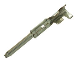
these are crimp pins - cable is crimped onto the pin.
They normally have a tab that catches on the plastic housing so you cant pull it out. To pull them out, you have a circular tube with an opening allow it onto the cable. The idea is that the tube pushes the tab away from the plastic shoulder so it can slide the pin out.
Is the tab broken? Which order do the wires do into the connector. It the tab is broken or bent, you can CAREFULLY glue the wire side to the plastic body often
Are these are a 1:1 connection and both ends correlate to each other, or plug into each other, but this is not always the case
these are the bits that grip the shoulders, This has two, but often flat connectors only have one and some round ones have one too
these are close https://cpc.farnell.com/search?st=jst , but also could be molex, or amp? https://www.ebay.co.uk/itm/TE-Connectivity-AMP-VAL-U-LOK-2-4-6-8-10-12-Way-PLUG-AND-SOCKET-Connectors-UK/121990365306
If you think someone may have access to one of these, and a few photos would help you, then do you not think by giving a manufacturers name and model of the tread mill people may assist you further?0 -
these are crimp pins - cable is crimped onto the pin.
They normally have a tab that catches on the plastic housing so you cant pull it out. To pull them out, you have a circular tube with an opening allow it onto the cable. The idea is that the tube pushes the tab away from the plastic shoulder so it can slide the pin out.
Is the tab broken? Which order do the wires do into the connector. It the tab is broken or bent, you can CAREFULLY glue the wire side to the plastic body often
Are these are a 1:1 connection and both ends correlate to each other, or plug into each other, but this is not always the case
these are the bits that grip the shoulders, This has two, but often flat connectors only have one and some round ones have one too
these are close https://cpc.farnell.com/search?st=jst , but also could be molex, or amp? https://www.ebay.co.uk/itm/TE-Connectivity-AMP-VAL-U-LOK-2-4-6-8-10-12-Way-PLUG-AND-SOCKET-Connectors-UK/121990365306
If you think someone may have access to one of these, and a few photos would help you, then do you not think by giving a manufacturers name and model of the tread mill people may assist you further?
Thanks, this is very helpful.
I've had a closer look and doesn't appear to be too much damage, the plastic housing is fine and all the wires except 1 still appear to be attached to the pins. I've attached a better photo. I'm guessing that the colours of wires will correspond to those that are still attached at the other side but I'll email the manufacturer to ask.
Should the wires which are still fine simply slide back in to the plastic housing? And I assume for the broken wire, I just need strip some back and crimp to a new pin?
https://photos.app.goo.gl/KLWxosNGLoQa8JJe80 -
Mmmm, I see and understand better.
The answer is how much you want to bodge it.
The safe answer is what voltage is running through that? is that cable ever going to be unplugged? If that wire breaks will someone be shot into infinity and beyond, and end up in heaven?
the white wire with the pin attached looks like it already has broken and the fixed, and covered with heat shrink - the black sleeve.
if that is mains voltage or a high voltage or high current, which i doubt, then you should do it properly.
I personally suspect it is low voltage (and I am a risk taker too). So I would take the pin and open the end up where the plastic sleeve gets gripped by the pin, using round nose plies in an appropriate position on the pin, open up the sleeve gripper with flat head jewellers screw driver and/or electronic side cutters (possibly best not to be ham-fisted). I then would strip 2-3mm of that sleeve insulation away from the wire and solder tack it onto the inside of the cable grip, or possible on top of the existing crimped cable - depends on cable and connector thickness and skill.
The black wire with the white stripe, looks like it is showing a gripping tag? with electronic side cutters, patience and dexterity, you are usually able to straighten, bend, and reposition these tags so that they can be used again. If the tags have broken off then it is another story
The other story... and I assume you know which wire go into which holes???
put the wires with tags in first then put the others in after, now the plug is fully populated, push it partial way into the socket, some pins will rise (the ones with no or bad gripper tags). with decent forceps, or pointy electronic pliers, or scriber, or thin nail take note of the standing pins, wiggle them gently in and firmly push down to the height of the others. then again push the connector further in, and repeat the previous steps.
Test it.
If it works hot glue gun down the tops of all the pins onto the top of the connector. do not glue the connectors together or force the glue down the pins
If I was to replace the connector and it was low voltage and current, I would seriously think about using D-25 computer serial connectors, and also short some pins via solder bridges for extra current if needed.
That red plastic housing - sometime has a manufacturers stamp or marking on it0 -
Mmmm, I see and understand better.
The answer is how much you want to bodge it.
The safe answer is what voltage is running through that? is that cable ever going to be unplugged? If that wire breaks will someone be shot into infinity and beyond, and end up in heaven?
the white wire with the pin attached looks like it already has broken and the fixed, and covered with heat shrink - the black sleeve.
if that is mains voltage or a high voltage or high current, which i doubt, then you should do it properly.
I personally suspect it is low voltage (and I am a risk taker too). So I would take the pin and open the end up where the plastic sleeve gets gripped by the pin, using round nose plies in an appropriate position on the pin, open up the sleeve gripper with flat head jewellers screw driver and/or electronic side cutters (possibly best not to be ham-fisted). I then would strip 2-3mm of that sleeve insulation away from the wire and solder tack it onto the inside of the cable grip, or possible on top of the existing crimped cable - depends on cable and connector thickness and skill.
The black wire with the white stripe, looks like it is showing a gripping tag? with electronic side cutters, patience and dexterity, you are usually able to straighten, bend, and reposition these tags so that they can be used again. If the tags have broken off then it is another story
The other story... and I assume you know which wire go into which holes???
put the wires with tags in first then put the others in after, now the plug is fully populated, push it partial way into the socket, some pins will rise (the ones with no or bad gripper tags). with decent forceps, or pointy electronic pliers, or scriber, or thin nail take note of the standing pins, wiggle them gently in and firmly push down to the height of the others. then again push the connector further in, and repeat the previous steps.
Test it.
If it works hot glue gun down the tops of all the pins onto the top of the connector. do not glue the connectors together or force the glue down the pins
If I was to replace the connector and it was low voltage and current, I would seriously think about using D-25 computer serial connectors, and also short some pins via solder bridges for extra current if needed.
That red plastic housing - sometime has a manufacturers stamp or marking on it
Thanks, it all sounds a bit complicated for me so I've got a guy I know coming to attempt a repair at the weekend!
The most frustrating thing is I only just bought it......the damage was done when I was attempting to get it in the van when I picked it up :laugh:0
This discussion has been closed.
Confirm your email address to Create Threads and Reply

Categories
- All Categories
- 353.5K Banking & Borrowing
- 254.2K Reduce Debt & Boost Income
- 455.1K Spending & Discounts
- 246.6K Work, Benefits & Business
- 603K Mortgages, Homes & Bills
- 178.1K Life & Family
- 260.6K Travel & Transport
- 1.5M Hobbies & Leisure
- 16K Discuss & Feedback
- 37.7K Read-Only Boards